An engine oil pump draws oil from the sump and moves it through the filter and engine lubrication passages. A typical oil pump assembly contains a housing, rotors or gears, an inlet, an outlet, a drive interface and a pressure-relief or control mechanism. The exact parts depend on whether the pump is a standalone unit or part of a timing cover, balance-shaft module or larger lubrication assembly.
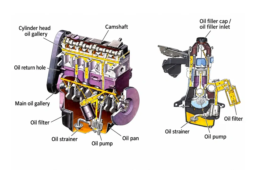
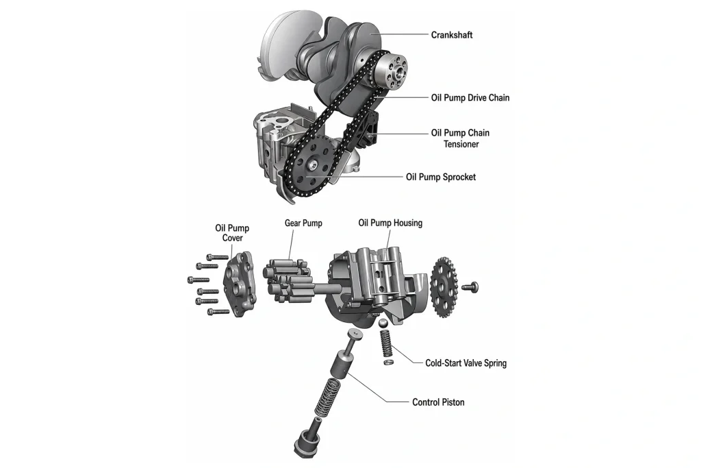
The diagram below identifies the main engine oil pump parts and oil-flow direction. The following sections explain how the pump works, how oil pump housings and assembly types differ, and which structural details buyers should compare before selecting a replacement.
How an Engine Oil Pump Works: Oil-Flow Diagram
An engine oil pump creates oil flow by increasing and reducing the volume inside its pumping chambers. Resistance in the lubrication circuit then produces oil pressure. The pump does not create a fixed pressure independently of the engine, oil temperature, bearing clearances and pressure-control system.
Oil sump → pickup and strainer → pump inlet → rotors or gears → pump outlet → oil filter → engine lubrication galleries → return to sump
- Oil enters the pump through the inlet after passing through the pickup and strainer.
- Rotating gears or rotors create expanding chambers that draw oil into the pump.
- The chambers become smaller near the outlet and force oil into the filter and lubrication galleries.
- A relief valve or variable-control mechanism limits pressure or changes pump output where the design permits.
The exact oil-flow route varies by engine. Some pumps connect directly to passages in the engine block, timing cover or balance-shaft module rather than using an external outlet pipe.
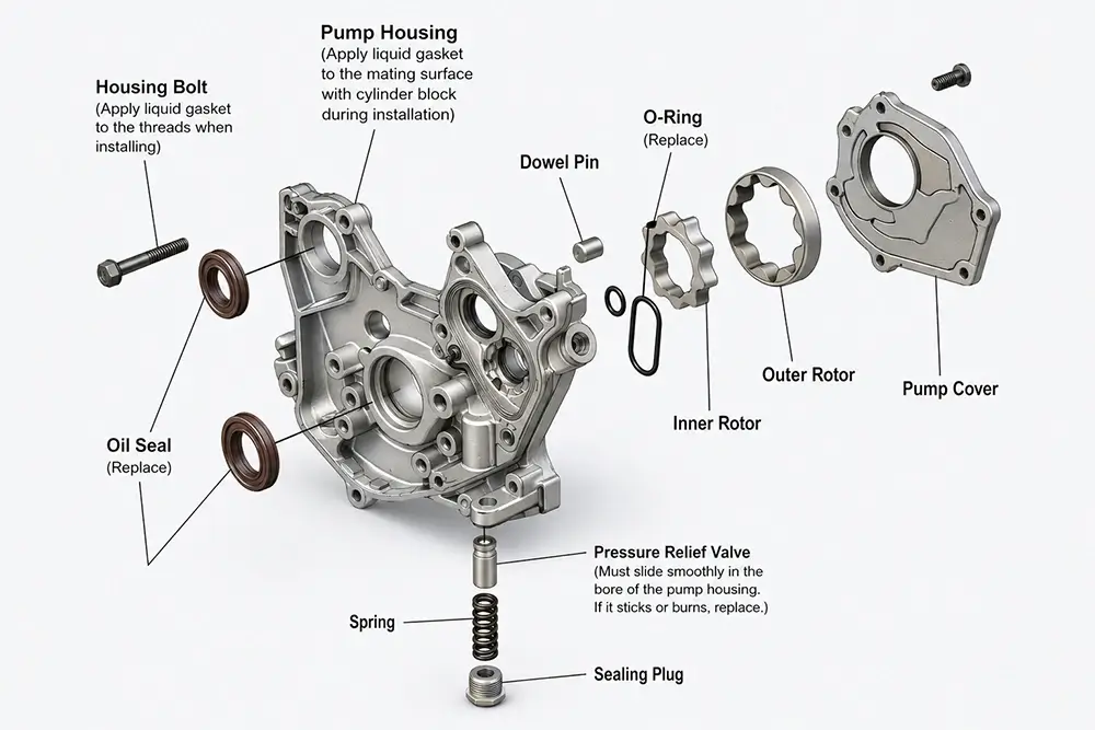
Main Engine Oil Pump Parts and Assembly Structure
| Engine oil pump part | Main function | What buyers should compare |
|---|---|---|
| Pump housing | Supports the pumping elements and connects the pump to the engine | Housing depth, bolt pattern, mounting face and oil passages |
| Rotors or gears | Create the changing chamber volume that moves oil | Profile, dimensions, clearance and visible wear |
| Drive interface | Transfers rotation from the engine to the pump | Chain, gear, crankshaft, shaft or module connection |
| Oil inlet and outlet | Receive oil from the sump and deliver it to the lubrication circuit | Port position, direction, pickup connection and passage alignment |
| Relief or control mechanism | Limits pressure or changes pump output | Valve position, spring, control chamber or solenoid provision |
| Cover and sealing surfaces | Close the pumping chamber and prevent leakage | Cover flatness, gasket surface, O-ring position and fasteners |
| Integrated components | Connect the pump to a wider engine assembly | Timing cover, balance shaft, pickup, housing and included accessories |
Not every oil pump assembly contains these parts as separately replaceable components. The pump may be integrated into a timing cover, balance-shaft module or larger housing, so the complete supplied scope must be confirmed before ordering.
Common Engine Oil Pump Designs and Drive Types
| Pump design | Basic structure | Key identification points |
|---|---|---|
| Gerotor oil pump | An inner rotor turns inside an outer rotor with a different number of lobes, forming expanding and contracting chambers | Inner and outer rotor profile, housing, centre drive and cover |
| Gear oil pump | Meshing gears carry oil around the outside of the gears from inlet to outlet | Gear arrangement, shafts, housing depth and drive interface |
| Variable-displacement oil pump | A control mechanism changes effective displacement or pressure behaviour according to the engine-system design | Control mechanism, valve or solenoid provision, housing and application data |
| Module-integrated oil pump | The pump forms part of a balance-shaft module, front cover or another engine assembly | Complete module scope, mounting face, oil passages and included components |
Pump design and drive type are related but not identical. For example, a gerotor pump may be crankshaft-driven, chain-driven or integrated into a wider module. Buyers should therefore confirm both the internal pump design and the external drive interface.
Oil Pump Housing vs Complete Oil Pump Assembly

The oil pump housing supports the pumping elements and may also contain the inlet, outlet, internal oil passages, mounting face and pressure-control components. Two pumps can have a similar front appearance while using different housing depths, rear mounting faces, bolt patterns or oil-passage arrangements.
The term “oil pump assembly” does not always describe the same supplied scope. It may refer to the pump body alone, a pump with its housing and cover, or a larger module containing a timing cover, balance shaft, pickup or control component.
| Product description | Possible supplied scope | Required confirmation |
|---|---|---|
| Oil pump body | Pumping section without the complete housing or accessories | Cover, housing and seals included or excluded |
| Pump with housing | Pump body, housing, cover and internal passages | Mounting face, ports and drive interface |
| Timing-cover oil pump | Pump integrated into the engine front cover | Complete cover dimensions, passages and seals |
| Balance-shaft oil pump module | Pump combined with a balance-shaft assembly | Module boundaries, drive arrangement and included parts |
| Variable oil pump assembly | Pump with a mechanical, hydraulic or electronic control system | Control valve, solenoid and related components included or excluded |
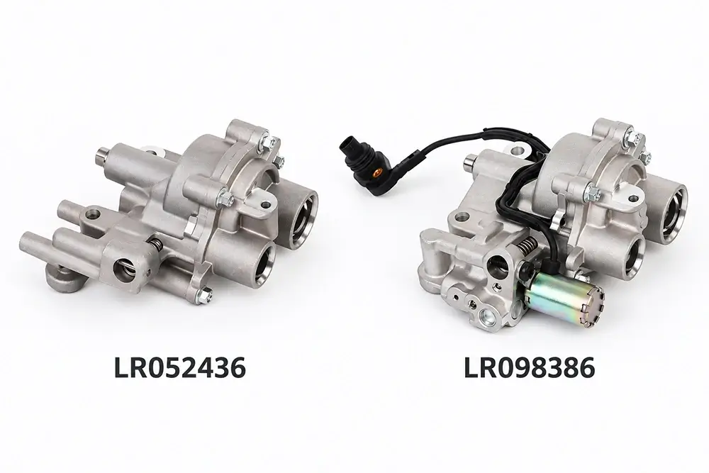
Current Wellgine examples show why assembly scope must be checked. The BMW N20 counterbalance-shaft oil pump assembly is supplied as a wider module, while the BMW B46/B48 11417624135 oil pump and LR087668 oil pump use their own application-specific housings and mounting structures. Confirm the OE reference, engine code and supplied components before comparing quotations. For a Jaguar Land Rover application example, the LR098386 oil pump page shows the housing and drive-interface views to compare. Confirm the required control components, seals and accessories as part of the quotation.
Need to confirm whether your requirement is a pump body or a complete oil pump assembly? Send the OE number, engine code and front and rear photographs for review.
Structural Conditions That Can Affect Oil Pump Performance
Oil-pump performance can be affected by excessive rotor or gear clearance, housing wear, a damaged drive interface, restricted inlet flow, a sticking relief valve or poor sealing. These conditions may reduce oil delivery, cause internal leakage or interrupt pump operation.
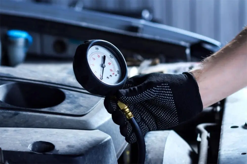
A warning light, noise or low-pressure reading does not prove that the pump is the cause. Oil level, viscosity, pickup restrictions, pressure-sensor faults and internal engine clearances should also be checked. For diagnosis boundaries, review the guide to engine oil pump failure symptoms.
How to Identify the Correct Engine Oil Pump
Structure should be checked together with application information. Use the following sequence before approving an oil pump:
- Confirm the complete OE number and any verified superseding reference.
- Confirm the engine code, production period and relevant vehicle application.
- Identify the pump design and drive method.
- Compare the housing depth, rear mounting face, bolt pattern and oil passages.
- Confirm whether the requirement is pump-only or a complete oil pump assembly.
- Provide front, rear, drive-side and oil-port photographs when catalogue information is incomplete.
| Identification check | Purpose |
|---|---|
| OE number | Initial product identity and cross-reference |
| Engine code | Application and engine-version confirmation |
| Pump design | Gerotor, gear, variable or integrated structure |
| Drive interface | Mechanical compatibility with the engine |
| Housing and mounting face | Physical fitment and passage alignment |
| Oil inlet and outlet | Lubrication-circuit compatibility |
| Assembly scope | Commercial and delivery confirmation |
| Photographs or sample | Physical verification where catalogue data is incomplete |
For the complete OE-number, engine-code and application confirmation process, follow our engine oil pump sourcing guide.
Inspection Focus for Oil Pump Structure
Inspection requirements should follow the approved drawing, reference sample and agreed project specification. Applicable checks may include:
- OE reference and product identity;
- housing dimensions and rear mounting-face condition;
- rotor, gear and drive-interface structure;
- inlet, outlet and internal passage positions;
- relief, control and sealing components where applicable;
- assembly completeness, cleanliness and packaging.
Broader batch inspection and traceability information is available on the Wellgine engine parts quality-control page.
Frequently Asked Questions
What are the main parts of an engine oil pump?
The main parts normally include the pump housing, rotors or gears, drive interface, oil inlet, oil outlet, pressure-relief or control mechanism, cover and sealing surfaces. Some pumps are integrated into a timing cover or balance-shaft module.
What is an oil pump assembly?
An oil pump assembly may include the pump body, housing, cover, drive components, pressure-control parts and seals. In some applications, it may also form part of a timing cover, balance-shaft module or larger lubrication unit.
What is the function of the oil pump housing?
The housing supports the pumping elements and may contain the inlet, outlet, internal passages, mounting face and pressure-control components. Housing depth, bolt pattern and passage layout must match the engine.
How does an engine oil pump work?
Rotating gears or rotors create expanding chambers that draw oil into the pump and contracting chambers that discharge it. Resistance in the engine lubrication circuit produces oil pressure.
What is the difference between a gerotor and a gear oil pump?
A gerotor pump uses an inner and outer rotor to form changing-volume chambers. A gear pump uses meshing gears to move oil from the inlet side to the outlet side.
Is an oil pump the same as a complete oil pump assembly?
Not always. “Oil pump” may describe the pump body only, while a complete assembly may include the housing, cover, drive components, pickup connection, control parts or an integrated module.
Request an Engine Oil Pump Assembly Review
Wellgine supplies selected engine oil pumps and complete oil pump assemblies for international B2B buyers. To review an application, send the OE number, engine code, original-pump photographs, required assembly scope, quantity, packaging requirement and destination market. Front and rear photographs are particularly important when two housings appear similar.