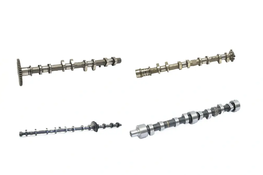
A camshaft is commonly made from chilled or hardenable cast iron, ductile iron, forged steel or machined steel billet. No material is automatically best. Durability depends on the specified material grade, lobe and journal surface hardness, hardened depth, grinding accuracy, surface finish and valve-train application.
For replacement camshaft sourcing, buyers should compare the finished-part specification—not only a “cast iron,” “steel” or “billet” label. The material, heat-treatment method and inspection requirements must work together to produce the required surface condition, dimensional accuracy and application compatibility.
What Are Camshafts Made Of?
Camshafts must meet two different mechanical requirements. The lobes and journals need working surfaces that can resist repeated contact, sliding and wear. At the same time, the complete shaft needs sufficient strength and toughness to resist bending, fatigue and local damage.
This creates an important engineering balance: wear-resistant working surface + adequately tough supporting material.
A surface that is too soft for the intended application may wear prematurely and alter the lobe profile or journal condition. However, selecting the highest possible hardness is not the solution. An unsuitable or poorly controlled hardened layer can crack, wear unevenly or be reduced during final grinding.
The appropriate material and treatment depend on the original engine design, valve-train load, follower type, lubrication conditions, manufacturing route and specified inspection requirements.
Camshaft Materials: Quick Comparison
| Material route | How the working surface is produced | What buyers should verify |
|---|---|---|
| Chilled cast iron | A wear-resistant lobe surface is formed through controlled chilling during casting | Material grade, chilled layer, lobe profile and surface finish |
| Hardenable or ductile cast iron | The cast blank may receive a separate surface-hardening process | Material grade, treatment method, surface and core condition, and hardened depth |
| Billet steel | The camshaft is machined from steel stock and heat-treated according to the application | Actual steel grade, heat treatment, case depth, distortion control and final grinding |
| Forged steel | A forged blank is machined and heat-treated to the required specification | Steel grade, forging route, heat treatment and final dimensional accuracy |
The correct choice depends on the original application. Material terminology alone does not confirm durability, fitment or finished-part quality.
What Is the Best Material for a Camshaft?
There is no single camshaft material that is automatically best for every engine. Chilled cast iron, hardenable or ductile iron, forged steel and billet steel can all be suitable when the material grade, manufacturing route, heat treatment and finished dimensions match the intended valve-train application.
The correct decision should be based on the original component specification and operating requirements. Relevant factors include follower type, lobe contact load, journal design, lubrication conditions, required core strength, surface hardness, hardened depth, distortion control and final grinding accuracy.
For replacement-part sourcing, buyers should not approve a camshaft only because it is described as steel, forged, billet or chilled iron. The finished component should be evaluated using the confirmed application, material documentation, hardness requirements, dimensional inspection and surface condition.
A more useful sourcing question is therefore not “Is steel better than cast iron?” but “Does the selected material and treatment process reproduce the required finished-part performance for this engine application?”
Cast Iron Camshaft Materials
“Cast iron camshaft” is a broad description. Different iron grades, alloy additions, graphite structures and casting processes can produce different strength, machinability, hardness and wear characteristics.
A procurement specification should therefore identify more than the words “cast iron.” Where applicable, it should define the material family, surface-treatment route, required hardness, hardened depth and relevant inspection method.
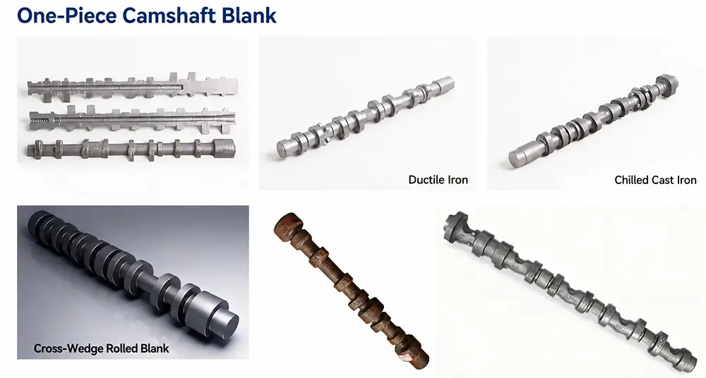
Chilled Cast Iron Camshafts
Chilled cast iron is produced by controlling the cooling of selected areas during casting. Rapid cooling at the lobe surface can create a harder and more wear-resistant local structure while the rest of the camshaft retains different properties.
This allows wear resistance to be introduced during the casting process rather than relying entirely on a separate surface-hardening operation. The result still depends on controlled casting conditions, lobe geometry, chilled-layer consistency, machining allowance and final grinding.
For sourcing and quality review, buyers should confirm:
- The specified cast-iron grade or approved material standard
- Whether the lobes use a controlled chilled surface
- The required chilled or hardened depth where specified
- Lobe-profile and journal-dimensional requirements
- Final grinding and surface-finish condition
- The applicable drawing, sample or inspection specification
A chilled surface does not by itself confirm that the complete camshaft meets the required dimensions or application.
Hardenable and Ductile Cast Iron Camshafts
Not all cast camshafts rely on chilling. Some cast-iron materials may receive induction hardening, flame hardening or another specified treatment after casting. Ductile or spheroidal-graphite iron may also be selected when the application requires a different balance of strength, toughness, machinability and response to heat treatment.
Two camshafts can therefore both be described as cast iron while having different core properties, heat-treatment requirements, hardness profiles and wear behaviour. Buyers should not substitute one material or manufacturing route for another without confirming the original specification and finished-part requirements.
Steel Camshaft Materials
Steel camshafts may be produced from billet stock, forged blanks or other approved starting forms. The word “steel” does not identify the actual alloy grade, manufacturing route or heat-treatment condition.
For a meaningful comparison, buyers should confirm the steel grade, blank-production route, heat treatment, hardened depth, final grinding allowance and finished geometry.
Billet Steel Camshafts
A billet camshaft is machined from solid steel stock rather than cast directly into a near-final camshaft shape. This route can provide manufacturing flexibility for specialised designs, lower-volume projects or applications where dedicated casting tooling is not appropriate.
However, “billet” describes the starting form and manufacturing route. It does not identify one universal steel grade or quality level. Two billet camshafts may use different steels, heat treatments, case depths and finishing processes.
When evaluating a billet camshaft, buyers should confirm:
- Actual steel grade and material condition
- Heat-treatment method
- Surface and core requirements
- Effective hardened or case depth
- Grinding allowance after treatment
- Lobe profile, journal dimensions and run-out
- Final surface finish
Forged Steel Camshafts
A forged steel camshaft begins with a blank shaped through a forging process before machining. This differs from machining the complete form from billet stock. Forging can affect material flow, blank geometry, production volume, machining allowance and process planning.
A forged label alone does not prove the quality of the finished part. Buyers still need evidence that the material, treatment, dimensions, lobe geometry and surface condition comply with the approved specification.
A billet or forged steel camshaft is not automatically superior to a cast camshaft. The correct evaluation should compare the complete material and manufacturing specification.
Camshaft Surface Hardness, Core Hardness and Hardened Depth
Camshaft hardness is often represented by one number without explaining where or how it was measured. This can be misleading because a camshaft may intentionally have different properties at the working surface, transition zone and core.
Surface Hardness vs Core Hardness
Surface hardness describes the resistance of the lobe or journal working surface to indentation and wear. Core hardness relates to the supporting material below the surface. The surface needs sufficient wear resistance, while the material below it must provide appropriate support and toughness.
A complete requirement may need to identify:
- Surface-hardness range
- Core-hardness range where applicable
- Test position and test method
- Effective hardened or case depth
- Material and heat-treatment condition
- Applicable drawing or specification
Why Higher Hardness Is Not Always Better
Maximum hardness is not the manufacturing objective. A camshaft operates as part of a contact system that includes the lobe, follower, tappet or rocker, engine oil, surface finish, contact geometry, load, temperature and operating speed.
A surface condition suitable for one engine or follower design may not be appropriate for another. Excessive or unsuitable hardness may also increase sensitivity to cracking or produce an incompatible contact condition.
The correct question is not “Which camshaft has the highest hardness value?” It is: Does the camshaft meet the specified material, hardness, depth, surface and valve-train requirements for the intended application?
How Hardness and Hardened Depth Should Be Verified
A surface reading does not describe the complete hardened layer. Effective hardened or case depth indicates how far the required hardness or metallurgical condition extends below the surface.
If the hardened region is too shallow, later grinding or service wear may expose material with different properties. The hardness test method must also match the material and hardened-layer thickness. Depending on the specification, testing may involve Rockwell, superficial hardness or microhardness measurements across a prepared section.
A useful hardness report should identify:
- Test method and location
- Measured value
- Required value or range
- Applicable specification
- Hardened or case-depth result where required
A standalone hardness number without this context has limited procurement value.
Camshaft Heat Treatment Methods
The heat-treatment route must be selected according to the base material, camshaft design, working-surface requirements and final manufacturing sequence.
Induction Hardening
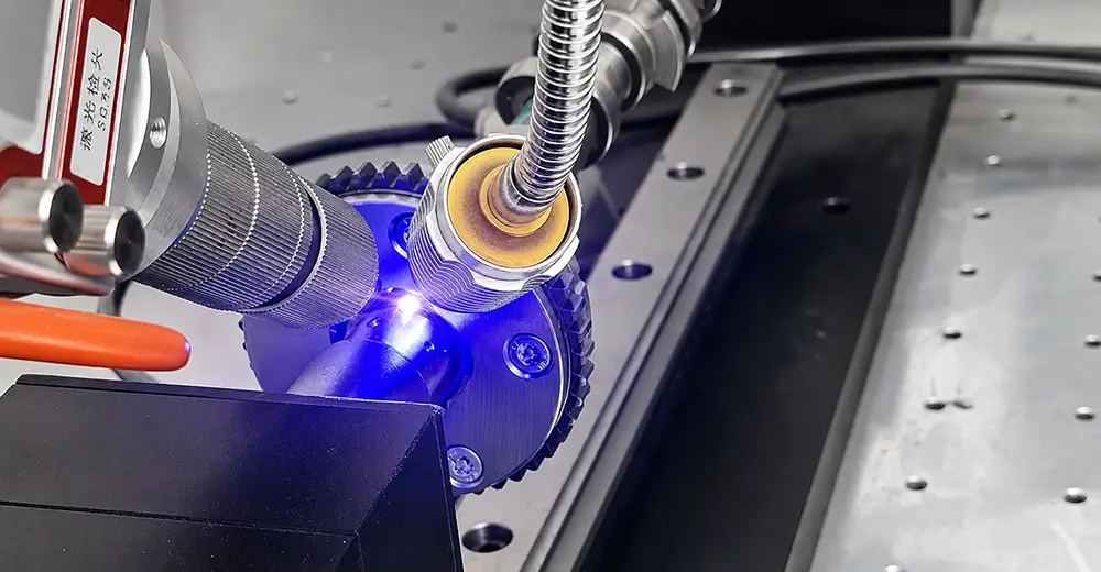
Induction hardening uses electromagnetic induction to heat selected areas before controlled cooling. For camshafts, it can harden defined working regions such as lobes or journals without treating the complete shaft identically.
Important variables include the heating pattern, temperature distribution, heating time, quenching conditions, hardness uniformity, hardened depth, distortion and final grinding allowance. The description “induction hardened” does not confirm that these variables meet the finished-part specification.
Nitriding
Nitriding introduces nitrogen into the surface of a suitable ferrous material to create a hardened case. Depending on the material and process, it can produce a wear-resistant surface at a comparatively moderate processing temperature.
The result depends on the steel composition, previous heat treatment, nitriding method, treatment time, case depth, compound-layer condition and post-treatment finishing. Buyers should confirm that the process is compatible with the specified material and verified on the finished part.
Carburising and Case Hardening
Carburising increases the carbon content near the surface of a suitable steel before hardening. This can create a wear-resistant case supported by a core with different properties.
The manufacturer must control surface hardness, case depth, core condition, distortion, grinding allowance and final dimensional accuracy. Different steel grades respond differently, so the treatment should be specified together with the material.
How Heat Treatment, Grinding and Surface Finish Work Together
Heat treatment and precision machining cannot be treated as unrelated production stages. Hardening can affect dimensions, straightness, residual stress and surface condition.
Final grinding must allow the camshaft to reach its specified lobe profile, journal dimensions, run-out and surface condition without removing an excessive amount of the hardened layer.
A typical controlled sequence may include:
Blank production → rough machining → heat treatment → correction where required → precision grinding → surface finishing → inspection
Hardness alone cannot compensate for an incorrect lobe profile or poor surface finish. Finished inspection may therefore need to consider:
- Lobe lift and profile
- Base-circle geometry
- Journal diameter and position
- Overall run-out and straightness
- Surface roughness and grinding marks
- Oil holes and grooves
- Timing-end and sensor-related features
For information about production and inspection capabilities, review Wellgine’s engine parts manufacturing information and confirm the applicable requirements for the specific project.
What Causes Premature Camshaft Wear?
Premature camshaft wear should not automatically be attributed to the base material or one hardness value. Several manufacturing, application and operating factors can contribute.
Manufacturing Factors
- Unsuitable material or material condition
- Incorrect or inconsistent heat treatment
- Inadequate surface hardness or hardened depth
- Incorrect lobe geometry
- Poor grinding or surface finish
- Dimensional error or excessive run-out
Application Factors
- Incorrect replacement camshaft
- Intake and exhaust positions being confused
- Incorrect bank or engine version
- Mismatched follower, tappet or rocker component
- Incorrect phaser, sprocket or timing-end interface
Operating and Installation Factors
- Insufficient lubrication or blocked oil passages
- Contaminated engine oil
- Installation or assembly error
- Abnormal valve-train loading
- Damage to related components
Premature wear should therefore be investigated as a material, manufacturing, application and lubrication issue rather than being attributed to hardness alone.
What B2B Buyers Should Verify Before Sourcing
Replacement camshaft evaluation should be completed in two stages. First confirm the identity and application of the part. Then confirm how the finished part should be manufactured and inspected.
Product Matching Information
Buyers should provide:
- Complete OE or reference number
- Engine code
- Vehicle application and production period
- Intake or exhaust position
- Bank position where applicable
- Photographs of the complete shaft and both ends
- Lobe, journal, oil-hole and sensor-related features
- Timing-gear or phaser interface
- Original sample or drawing where required
- Bare camshaft or assembly requirement
- Required quantity and packaging
Material and hardness cannot identify whether a camshaft is for the intake or exhaust position. Position should be confirmed using the OE reference, engine code, application data, end structure and other physical features.
Where a camshaft connects to a phaser or another variable-timing component, the relationship between the shaft, oil passages, timing interface and variable valve timing system should also be confirmed.
Manufacturing and Inspection Requirements
Depending on the product and purchasing agreement, buyers may need to confirm:
- Material grade
- Casting, forging or billet route
- Heat-treatment process
- Surface and core hardness where specified
- Effective hardened or case depth
- Lobe profile and journal dimensions
- Straightness and run-out
- Surface finish
- Oil holes and grooves
- Visual or crack inspection where specified
- Batch and inspection records
- Packaging and rust protection
The inspection plan should follow the confirmed drawing, approved sample and agreed product specification. Buyers should not assume that every camshaft requires the same material, hardness or test package.
For the complete RFQ and application-confirmation process, use the Camshaft Sourcing Guide before requesting a quotation.
Request Camshaft Review
Need to confirm a replacement camshaft? Send the OE number, engine code, intake or exhaust position, product photographs, required quantity and any material, hardness or inspection specification.
Frequently Asked Questions
What material are camshafts made from?
Camshafts may be made from chilled or hardenable cast iron, ductile iron, forged steel or machined steel billet. The appropriate material depends on the engine design, valve-train load, manufacturing route and specified surface treatment.
Is cast iron or steel better for a camshaft?
Neither material is automatically better for every application. A finished camshaft should be evaluated by its material grade, heat treatment, hardened depth, lobe profile, surface finish and compatibility with the intended engine.
What is the difference between camshaft surface hardness and core hardness?
Surface hardness describes the wear-resistant working area of the lobes or journals. Core hardness relates to the supporting material below the surface. They perform different functions and should not be represented by one hardness value.
Which heat treatment is used for camshafts?
Depending on the material and application, camshafts may use induction hardening, nitriding, carburising or another specified surface-treatment route. The process must be matched to the base material and finished-part requirements.
How to Evaluate Camshaft Material and Manufacturing Quality
Camshaft durability cannot be judged from a “cast iron,” “steel” or “billet” label alone. Buyers should confirm the material grade, manufacturing route, heat treatment, surface and core requirements, hardened depth, grinding accuracy and application before approving a replacement camshaft.
The final inspection plan should follow the confirmed drawing, approved sample and agreed product specification.