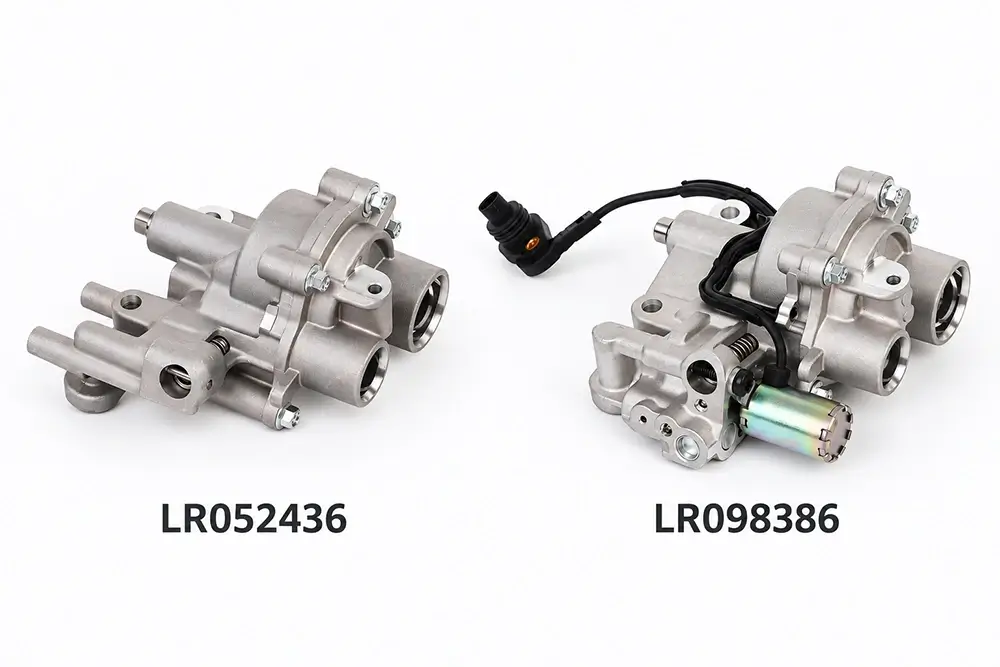
The Mercedes-Benz M270 and M274 timing systems combine a conventional mechanical timing drive with hydraulically controlled variable valve timing. For parts buyers, this can make the front of the engine look more complicated than it really is because several components — the camshaft, camshaft adjuster, VVT control valve, position sensor and timing-chain drive — all contribute to the same timing-control result.
The key is to separate their roles before trying to identify or replace a part. The camshaft opens the valves. The camshaft adjuster changes the angular relationship between the camshaft and the timing drive. The VVT control valve directs engine oil to the adjuster. The camshaft position sensor then reports the resulting position back to the engine-management system.
Seen in this order, the M270/M274 system becomes easier to understand as a connected mechanical, hydraulic and electronic control chain rather than a collection of unrelated timing components.
The main M270/M274 timing-control components can be separated by function before any replacement part is selected.
| Component | Main function | Matching focus |
|---|---|---|
| Camshaft | Provides the mechanical profile that operates the valves | OE number, engine application and intake or exhaust position |
| Camshaft adjuster | Changes the angular position of the camshaft | OE number, intake/exhaust position, oil-port layout and locked position |
| VVT control valve | Directs pressurised oil towards the adjuster | Connector, valve-body structure, OE number and engine application |
| Camshaft position sensor | Reports actual camshaft position to the control system | Connector, mounting position and exact engine application |
| Timing chain drive | Establishes the basic mechanical relationship between the crankshaft and camshafts | Engine version, chain layout, guides, tensioner and timing procedure |
A fault in one part of this chain can affect the behaviour of the complete timing system. The fault code or visible symptom should therefore be diagnosed before a camshaft, adjuster or control valve is selected for replacement.
How the M270/M274 Timing-Control System Fits Together
The timing system can be understood as three layers that operate together.
The mechanical layer begins with the crankshaft and timing chain. The chain drives the camshaft adjuster, the adjuster is connected to the camshaft, and the camshaft operates the valve train:
Crankshaft → timing chain → camshaft adjuster → camshaft → valves
The hydraulic layer provides the variable-timing function. Engine oil is routed through the cylinder-head timing circuit and a VVT control valve towards the adjuster:
Engine oil supply → VVT control valve → camshaft oil passages → adjuster chambers
The electronic layer links the requested timing change with the actual result:
Engine control unit → VVT command → hydraulic adjustment → camshaft movement → camshaft position feedback
These three paths are not independent. If basic mechanical timing is wrong, hydraulic adjustment cannot correct the entire error. If oil flow is restricted, the adjuster may not respond correctly even when the camshaft itself is mechanically sound. If position feedback is incorrect, the engine-management system may report a timing-control problem even though the hydraulic components are capable of moving.
This is why system-level understanding is useful before an M270/M274 camshaft or adjuster is selected for replacement.
The Camshaft Provides the Mechanical Valve Motion
The camshaft is the mechanical link between rotational timing and valve movement. Its lobes act on the valve train, determining when and how the valves open and close according to the cam profile.
Its basic function remains straightforward:
camshaft rotation → cam-lobe movement → valve-train movement
Variable valve timing does not change that fundamental job. Instead, the VVT system changes the camshaft’s angular position relative to the crankshaft so that valve events occur earlier or later within the range designed for the engine.
This distinction matters when parts are being matched. A camshaft may sit directly beside a camshaft adjuster and share oil passages or mounting features with it, but it is still a separate component with its own OE reference, intake or exhaust position and physical structure.
For supported replacement applications, buyers can review Wellgine’s Mercedes-Benz Camshafts range.
The Camshaft Adjuster Connects Mechanical Timing with Variable Timing
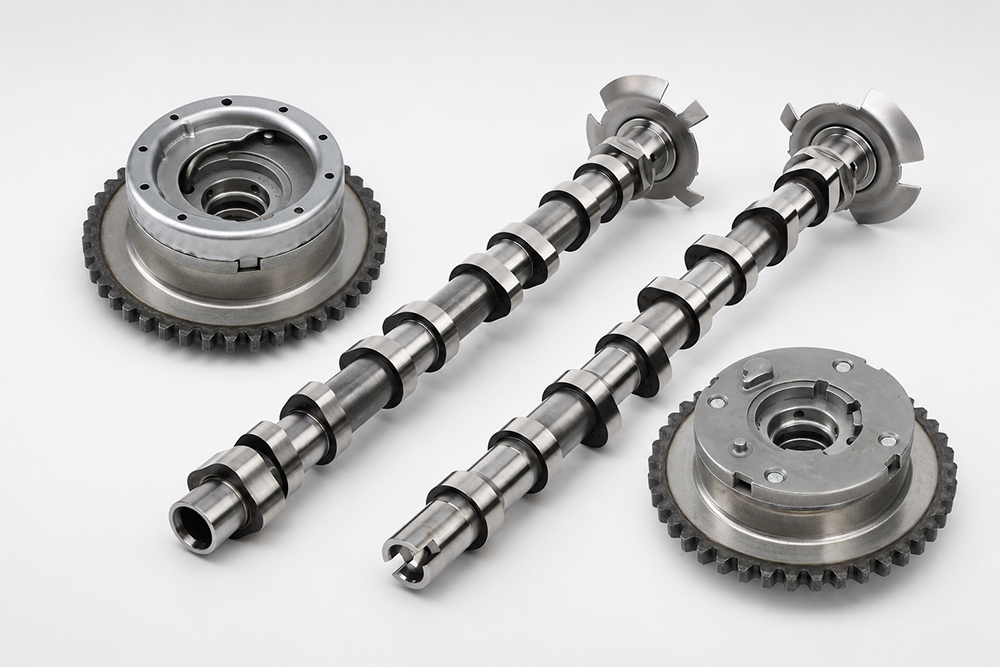
The camshaft adjuster — also commonly called a camshaft phaser or VVT gear — forms the bridge between the timing-chain drive and the camshaft. The outer part of the adjuster follows the timing drive, while the internal rotor is connected to the camshaft.
In a typical hydraulic vane-type design, oil pressure acts inside working chambers between the rotor and housing. By directing oil to the appropriate side of the mechanism, the system can move the rotor relative to the housing and change camshaft phase.
A typical adjuster may include an outer housing or sprocket section, an internal rotor, hydraulic chambers, oil passages, mechanical travel limits and, in many designs, a locking mechanism. These elements explain why the adjuster is more than a simple timing sprocket.
However, the presence of the same general components does not make all M270/M274 adjusters interchangeable. Adjustment range, locking position, internal oil routing and calibration can vary by application. Exact position and OE matching therefore remain essential.
VVT Oil Flow Is What Allows the Adjuster to Move
The adjuster cannot change position without controlled oil flow. This is where the VVT control valve, sometimes described as an adjustment solenoid, becomes important.
The control valve does not rotate the camshaft directly. Instead, it regulates which hydraulic path is available to the adjuster. In simplified form:
oil supply → VVT control valve → selected oil passage → adjuster chamber
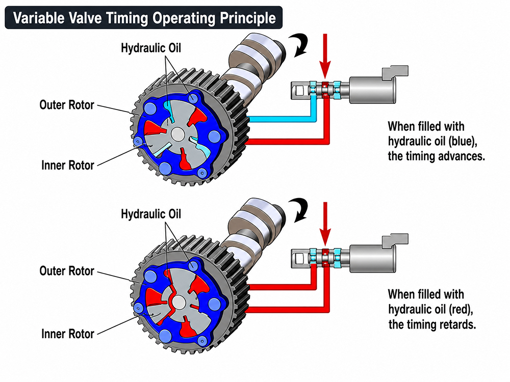
Once the appropriate chamber receives oil pressure, hydraulic force acts on the rotor and changes its position relative to the housing. Oil on the opposite side is controlled or displaced according to the internal circuit, allowing the camshaft to move towards the commanded timing position.
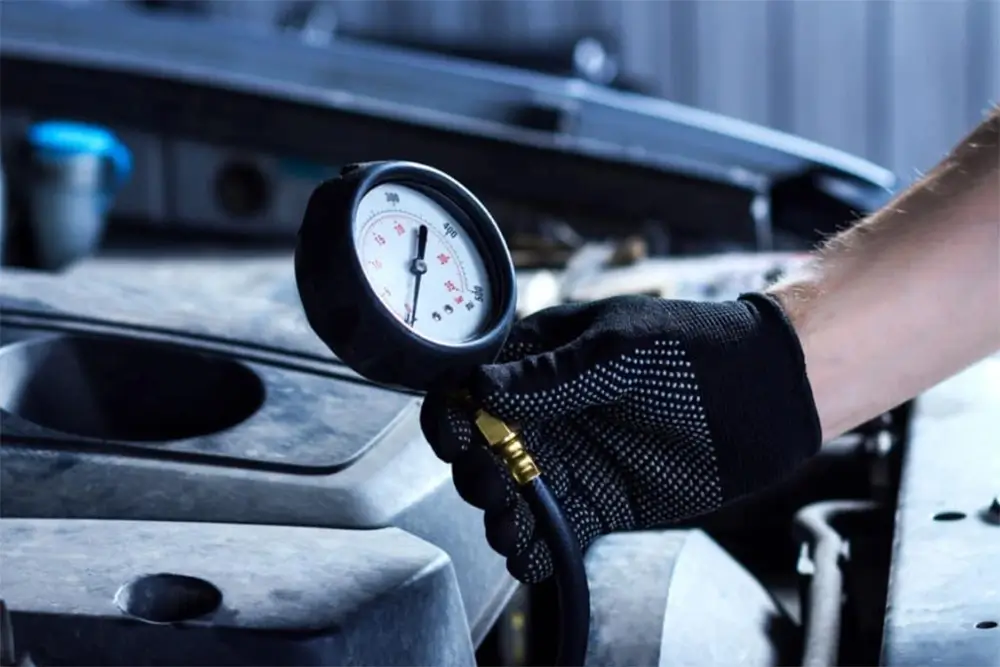
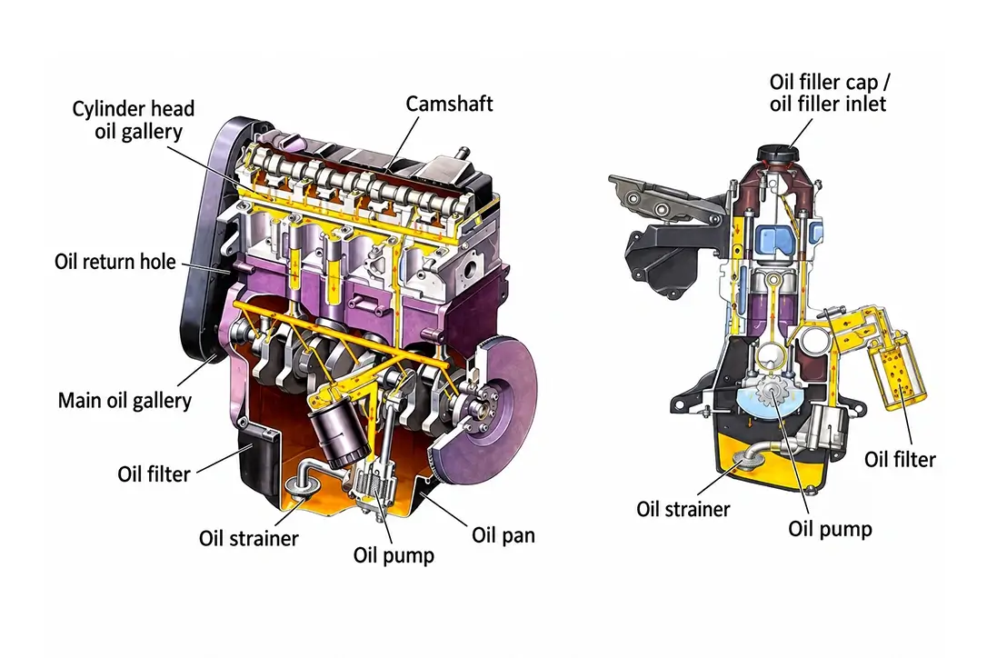
This is why engine oil is part of the timing-control system rather than simply a lubrication medium. The M270/M274 timing circuit depends on oil reaching the cylinder head, passing through the relevant control path and arriving at the adjuster in the correct way.
A useful system-level oil path is:
oil pump → engine oil circuit → cylinder-head oil supply → VVT control valve → camshaft / adjuster oil passages → hydraulic working chambers
The exact route and operating values depend on the engine variant and component design. For that reason, this guide does not apply one universal oil-pressure, viscosity, temperature or control threshold to every M270/M274 application.
For a broader explanation of how VVT control valves, phasers and feedback work together, see the Variable Valve Timing (VVT) System Guide.
Intake and Exhaust Adjusters Must Be Matched by Position
Once the operating principle is clear, the next sourcing issue is position matching. Intake and exhaust adjusters can belong to the same engine family and still differ internally or at their mounting and oil interfaces.
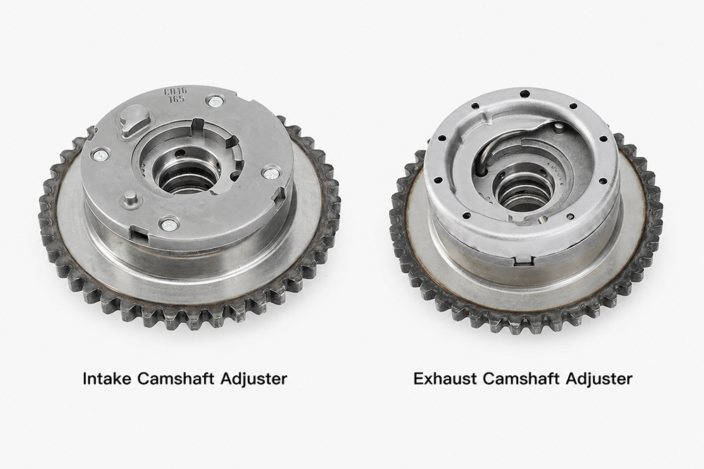
Possible differences include internal oil routing, base or locked position, direction of hydraulic adjustment, timing marks, sprocket geometry, central mounting arrangement, camshaft interface and oil-port position.
This means overall appearance is not enough. A distributor should not identify a component simply as an “M270/M274 timing gear”. A safer matching sequence is:
position → OE reference → engine/application data → physical structure
The same principle applies where a camshaft and adjuster appear to form a familiar pair. Similarity in diameter or timing-chain tooth profile does not prove that the hydraulic interfaces or internal control characteristics are the same.
Mechanical, Hydraulic and Feedback Problems Need to Be Separated
The relationship between these components also explains why a timing-control fault should not automatically be assigned to the camshaft or adjuster.
Mechanical timing problems
The timing chain establishes the base relationship between the crankshaft and camshaft drive. If basic mechanical timing is incorrect, the variable-timing system is starting from the wrong reference. A phaser cannot simply compensate for an unlimited mechanical timing error.
Hydraulic VVT problems
The adjuster depends on controlled oil flow. A restricted oil passage, control-valve problem, unsuitable oil condition or internal adjuster fault can all affect response. A hydraulic timing complaint therefore does not prove by itself that the phaser is defective.
Position-feedback problems
The engine-management system also needs to know whether the requested timing change has actually occurred. Camshaft-position sensing provides this feedback and closes the control loop:
command → hydraulic control → adjuster movement → camshaft position → feedback
If requested and actual positions do not agree, the cause can be mechanical, hydraulic, electrical, sensor-related or component-specific.
For parts buyers, the practical implication is simple:
a timing code does not by itself confirm camshaft failure, and it does not by itself confirm adjuster failure.
The underlying system should be diagnosed before a replacement component is selected.
Oil-Passage Geometry Is Part of Component Matching
Oil flow is not only a diagnostic issue; it is also a physical part-matching issue. Two camshafts or adjusters may look similar while using different hydraulic interfaces.
Relevant features can include central oil-feed passages, radial oil holes, annular grooves, oil-port orientation, sealing lands, bolt or centre-bore oil routing and the interface between the camshaft and adjuster.
If any of these features differ from the verified original part, the hydraulic circuit may not connect to the intended chamber even if the component appears dimensionally similar from the outside.
For this reason, replacement matching should compare both the external structure and the oil-routing features rather than relying only on overall size, sprocket shape or engine-family name.
M270/M274 Camshaft and Adjuster Reference Examples
The following Wellgine product references show how individual components fit into the wider timing-control system. They are examples of product-page ownership, not a universal parts list for every M270/M274 engine.
| Component role | Example Wellgine reference | System relationship |
|---|---|---|
| M270 intake camshaft | A2700501601 / 2700501601 | Mechanical valve-motion component |
| M274 intake camshaft | A2740500401 | Mechanical valve-motion component |
| Intake camshaft adjuster | A2700506100 | Hydraulic phase-adjustment component |
| Camshaft adjuster reference | A2700506200 | Adjuster / phaser reference; confirm exact position and application before ordering |
Exact OE-reference queries should remain with these product pages. This platform guide is intended to explain how the components relate to one another before the buyer moves to individual product matching.
For the wider commercial range, see Mercedes-Benz Camshaft Phasers.
M270/M274 Timing Marks and Torque Specifications
Timing-mark positions and tightening specifications must be confirmed for the exact M270 or M274 engine version and the applicable repair procedure. A single diagram or torque value should not be assumed to cover every camshaft, adjuster, central bolt, bearing cap or timing-drive fastener used across the complete engine family.
Before assembly, confirm the complete engine identification, intake and exhaust positions, installed camshaft and adjuster references, fastener type and whether the applicable procedure requires a new bolt, an angle-tightening stage or another replacement component.
The following information should come from the applicable Mercedes-Benz workshop procedure or another verified technical source:
- crankshaft positioning procedure;
- intake and exhaust camshaft timing marks;
- camshaft locking-tool position;
- camshaft adjuster base or locked position;
- central adjuster-bolt tightening procedure;
- camshaft-bearing or carrier tightening sequence;
- timing-chain tensioner installation procedure;
- any fasteners that must not be reused.
Do not use a general internet torque value solely because it is labelled for an M270 or M274 engine. The same engine family can contain production, fastener and component differences. An incorrect tightening value or timing position can damage the component or produce an incorrect mechanical timing relationship.
This page explains the relationship between the camshaft, adjuster, VVT oil circuit and position feedback. It should not replace the vehicle-specific workshop procedure required for engine assembly.
What Buyers Should Confirm Before Ordering
Once the buyer has identified whether the required part is a camshaft, adjuster or another VVT component, the final step is application confirmation.
For professional replacement-part matching, provide as much of the following information as possible:
- OE number on the original part;
- Mercedes engine code;
- M270 or M274 platform identification;
- vehicle model;
- production year or other production information where relevant;
- intake or exhaust position;
- VIN where required for application confirmation;
- photographs of the original part;
- front and rear structural views;
- oil-port and centre-bore details for adjusters;
- required quantity.
Where an OE reference has been superseded, the supersession should be checked against the relevant engine and vehicle application rather than assumed to apply across the complete M270/M274 platform.
The Key M270/M274 Timing-Control Relationship
The system is easiest to remember as a sequence of different jobs rather than a list of parts.
The timing chain provides the mechanical drive.
The camshaft operates the valves.
The camshaft adjuster changes camshaft phase.
The VVT control valve directs engine oil so that the adjuster can move.
The camshaft position sensor reports the result to the engine-management system.
For aftermarket distributors and professional engine-parts buyers, this system-level view reduces the risk of treating camshafts, adjusters and VVT control parts as interchangeable components.
Buyers can continue from this guide to Wellgine’s Mercedes-Benz Camshafts, Mercedes-Benz Camshaft Phasers and the Variable Valve Timing (VVT) System Guide for product-level and wider system information.
Technical reference note: The system-level descriptions in this guide reflect Mercedes-Benz technical documentation reviewed during research and established hydraulic VVT principles. Adjustment ranges, oil-pressure specifications, locking positions, control thresholds and diagnostic limits must be confirmed against the exact engine variant and applicable workshop documentation. This guide intentionally does not apply one universal value across all M270/M274 applications.