A camshaft phaser can look correct from the outside and still be unsuitable for a particular order.
For distributors, engine rebuilders and incoming-quality teams, receiving inspection should therefore do more than check whether a timing gear has arrived without obvious damage.
Before a batch is accepted into stock, inspectors should confirm three different questions:
Is this the correct phaser?
Has it arrived in acceptable physical condition?
Do the accessible mechanical and hydraulic features match the approved reference?
For many hydraulic camshaft phasers, practical incoming checks focus on the locking mechanism, oil passages, mounting and timing features, intake or exhaust position, OE or drawing reference, and visible manufacturing condition.
These checks do not replace application-specific functional testing. They provide a structured receiving-inspection layer before parts are released for inventory, assembly or further validation.
Camshaft Phaser Incoming Inspection Checklist
The incoming inspection should first confirm that the delivered phaser matches the approved order, position and supply scope. The mechanical and hydraulic checks should then be recorded against the approved sample, drawing or inspection specification.
The following checklist can be used as a receiving-inspection framework. Acceptance limits, test methods and sampling quantities must still follow the confirmed customer or project requirements.
| Inspection item | What to confirm | Suggested record |
|---|---|---|
| Part identity | Supplier number, internal number and OE reference | Number and marking photograph |
| Application | Engine code, platform or approved application | Order or project reference |
| Position | Intake/exhaust, left/right or bank position | Confirmed position |
| Supplied scope | Phaser only, bolt, washer, fasteners or matched set | Package-content record |
| External housing | Cracks, dents, corrosion, burrs and machining damage | Visual result and photographs |
| Sprocket teeth | Chipping, impact damage, abnormal wear or deformation | Visual result |
| Centre bore and mounting interface | Structure, dimensions and visible damage | Drawing or approved-sample comparison |
| Locking mechanism | Accessible locked position and abnormal free movement | Inspection result |
| Oil passages | Correct position, open passage and absence of contamination | Visual or specified inspection result |
| Timing and locating features | Timing marks, locating holes and trigger features | Approved-reference comparison |
| Threads and fixing surfaces | Damage, contamination and dimensional condition | Inspection result |
| Batch marking | Production or traceability marking | Recorded batch number |
| Packaging | Protection, labelling and quantity | Packaging and quantity record |
| Final disposition | Accepted, held for review or rejected | Inspector, date and disposition |
The checklist establishes the inspection sequence but does not create one universal acceptance limit for every phaser design. Rotation range, locking behaviour, dimensional tolerances and functional test conditions must come from the applicable drawing, approved sample or validated inspection specification.
What Should Camshaft Phaser Incoming Inspection Cover?
The checklist above can be organised into five main inspection areas: identity and position matching, external condition, locking-mechanism condition, oil-passage and sealing-interface condition, and comparison with the approved sample or specification.
The inspection should begin with identity.
A mechanically sound phaser is still a wrong part if the intake and exhaust versions have been mixed, the OE reference does not match the order, or the supplied assembly differs from the approved configuration.
For detailed part identification, see the Camshaft Phaser Identification Guide.
1. Confirm the Part Before Inspecting the Mechanism
Do not begin by rotating the phaser or testing the locking mechanism.
First confirm what has actually been delivered.
Record and compare:
- supplier or internal part number;
- OE-reference number where applicable;
- customer or project reference;
- engine code or platform where required;
- intake or exhaust position;
- left / right or bank position where applicable;
- quantity;
- production or batch marking;
- supplied components;
- approved sample or drawing revision.
This prevents a common incoming-inspection mistake: rejecting or accepting a part based on mechanical behaviour before confirming that it is the correct version.
2. Intake and Exhaust Position Must Be Matched Correctly
Camshaft phasers that belong to the same engine family can look very similar.
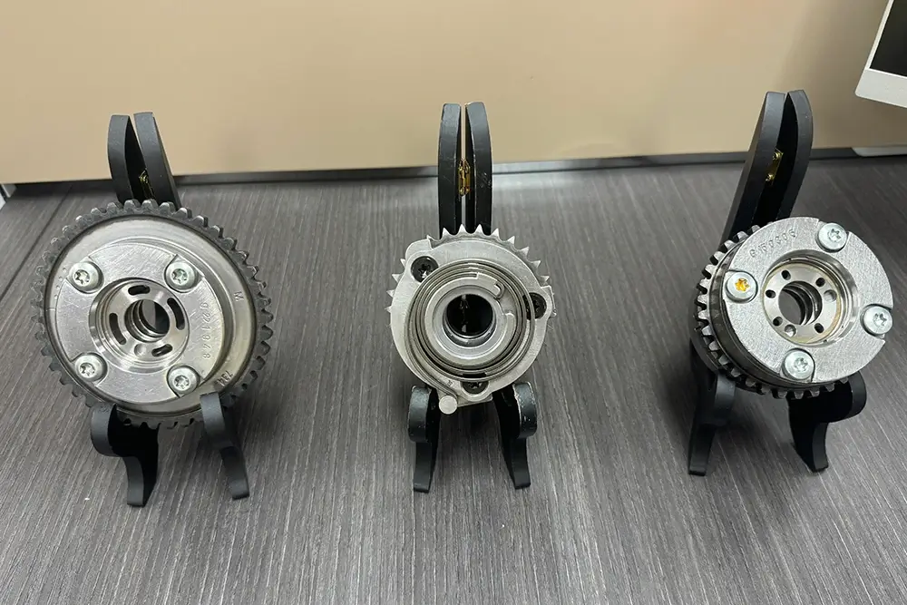
The differences may involve:
- timing marks;
- oil-port positions;
- locating features;
- hub geometry;
- sprocket orientation;
- locking position;
- sensor or trigger features;
- central fixing arrangement;
- or internal calibration.
The inspection team should therefore avoid identifying intake and exhaust phasers only by overall diameter or external appearance.
A receiving checklist should state the approved position explicitly.
For example:
Intake — confirmed
or
Exhaust — confirmed
rather than simply:
Camshaft phaser — correct
Where a left/right or Bank 1/Bank 2 distinction exists, that information should be controlled separately.
3. Compare the Supplied Scope
Incoming inspection should also confirm what is included with the phaser.
Depending on the product, the supply may consist of:
- phaser assembly only;
- phaser with central bolt;
- phaser with washer;
- intake and exhaust set;
- associated fasteners;
- packaging accessories.
Do not assume that two products with the same general phaser description include the same scope.
The approved order, drawing or sample should define what belongs in the package.
4. Inspect the Sprocket and External Housing
Before checking the hydraulic features, inspect the complete external surface.
Look for:
- damaged or chipped teeth;
- dents;
- impact marks;
- cracks;
- deformation;
- corrosion;
- burrs;
- abnormal machining marks;
- contamination;
- damaged threads;
- damaged mounting faces.
Timing sprocket teeth are functional surfaces.
Damage should not be dismissed as cosmetic simply because the phaser can still be rotated by hand.
The same applies to mounting and sealing faces. Local damage in these regions can affect assembly even when the external appearance of the part is otherwise acceptable.
5. Check the Central Bore, Threads and Locating Features
The interface between the phaser and camshaft is one of the most important matching areas.
Depending on the design, inspect the relevant:
- centre bore;
- bolt seat;
- internal or external thread;
- key or locating feature;
- pin hole;
- mating face;
- hub profile.
Compare these directly with:
- the approved drawing;
- master sample;
- confirmed original part;
- or controlled inspection specification.
Do not infer interchangeability because two phasers have the same sprocket diameter.
A small difference at the camshaft interface can make the part impossible to install or position correctly.
6. Understand What the Locking Pin Is Checking
Many hydraulic vane-type camshaft phasers use a locking mechanism to hold the internal rotor in a defined position under specific conditions.
A common design uses a spring-loaded locking pin that mechanically engages a corresponding seat or bore. Pressurised oil can act on the mechanism to release the pin when the VVT system operates.
However, the exact design differs between phaser families.
Incoming inspection should therefore not assume that:
- every phaser locks at the same angular position;
- every phaser should feel identical by hand;
- every locking pin is externally visible;
- or every phaser can be released using the same test procedure.
The correct behaviour must be defined by the part-specific reference.
7. Basic Locking-Pin Inspection
Where the design allows a non-destructive manual check, inspect whether the phaser is in the expected reference condition.
Depending on the approved procedure, this may include checking:
- whether the rotor is held at the specified base position;
- whether unexpected free movement exists while locked;
- whether the locking action feels consistent across the sample;
- whether the mechanism visibly or mechanically returns to its reference condition.
The purpose is not to force the phaser through its operating range.
The purpose is to identify obvious abnormalities such as:
- no apparent locking where locking is expected;
- excessive uncontrolled movement;
- sticking;
- inconsistent engagement;
- abnormal mechanical noise.
Any acceptance limit for rotational play must come from an approved product specification.
Do not create a universal “acceptable degrees of play” rule for all camshaft phasers.
8. Do Not Force a Locked Phaser by Hand
A locked phaser may intentionally resist relative rotation.
Excessive hand force or the use of tools can damage:
- the locking pin;
- locking seat;
- rotor;
- stop surfaces;
- housing;
- or internal sealing interfaces.
If the phaser requires hydraulic or pneumatic pressure to unlock during an approved bench procedure, use the specified procedure rather than attempting to overcome the mechanism mechanically.
Incoming inspection should never create damage while trying to detect damage.
9. Why Oil Passages Matter
A hydraulic camshaft phaser depends on controlled engine-oil flow.
Depending on the design, oil may be routed through:
- camshaft oil galleries;
- the central fixing bolt;
- rotor passages;
- advance chambers;
- retard chambers;
- control-valve passages;
- locking-pin release circuits.
Restricted, mis-machined or contaminated passages can therefore affect hydraulic operation even when the external phaser appears correct.
This makes accessible oil passages an important incoming-inspection point.
For the broader relationship between the phaser, oil-control valve and VVT system, see the Variable Valve Timing System Guide.
10. Visually Inspect Accessible Oil Ports
Inspect accessible oil openings under suitable lighting.
Look for:
- metal chips;
- machining debris;
- packaging contamination;
- rust;
- blocked holes;
- burrs at drilled passages;
- damaged edges;
- abnormal sealant or foreign material.
Where the inspection specification permits, confirm that the accessible passage configuration matches the approved part.
This is primarily a visual and structural check.
A visible oil hole does not prove that the complete internal hydraulic circuit is correctly connected or leak-free.
That requires a validated functional test.
11. Compare Oil-Passage Position, Not Just Hole Count
Counting the number of visible oil holes is not enough.
Two phasers can have a similar number of passages but differ in:
- angular position;
- diameter;
- depth;
- connection to internal chambers;
- sealing-land arrangement;
- central-bolt oil routing;
- or intake/exhaust function.
During receiving inspection, compare oil-port geometry to the approved reference.
Useful comparison points can include:
- hole location relative to locating features;
- port spacing;
- central-bore arrangement;
- sealing grooves;
- feed and return interfaces.
The exact dimensions should come from the controlled drawing or sample, not from a generic VVT reference.
12. Check for Burrs and Machining Residue
Oil ports and cross-drilled holes require particular attention because machining debris can remain in recessed areas.
Inspectors should look for:
- loose metal particles;
- sharp burrs;
- partially obstructed holes;
- swarf;
- damaged drilled edges.
If contamination is found, the response should follow the agreed quality procedure.
Do not simply remove contamination and accept the component if the finding indicates a wider batch-control issue.
The inspection record should preserve the evidence and affected quantity.
13. Inspect Sealing and Mating Surfaces
Hydraulic operation depends not only on internal passages but also on the interfaces that keep oil directed through the intended circuit.
Inspect relevant:
- annular sealing lands;
- machined faces;
- bolt interfaces;
- O-ring grooves where present;
- gasket or sealing surfaces;
- rotor/hub interfaces visible without disassembly.
Reject or quarantine criteria should be based on the controlled specification.
Surface damage in a hydraulic interface can be functionally more important than a cosmetic mark on a non-working external area.
14. Should Incoming Inspection Include an Air or Oil Test?
It can, but only when a validated part-specific procedure exists.
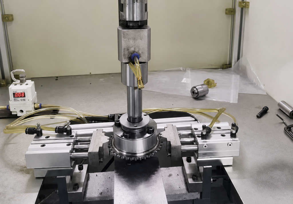
Technical cam-phaser designs commonly use pressurised oil to move internal elements and release locking mechanisms. Workshop procedures for some applications also use controlled pressure to verify unlocking and rotational response.
That does not mean one bench-test method can be applied to every incoming phaser.
Before using a functional test, define:
- which oil port receives pressure;
- test medium;
- test pressure;
- reference position;
- expected unlocking behaviour;
- permitted movement;
- leakage acceptance;
- return or re-locking behaviour;
- test duration.
Without those parameters, applying compressed air or oil is not a controlled quality test.
It is an experiment.
15. Never Use One Universal Pressure Test
A receiving team should not create a rule such as:
“All camshaft phasers must unlock at X bar.”
Different designs may have different:
- locking-pin springs;
- hydraulic areas;
- oil circuits;
- control-valve arrangements;
- rotational ranges;
- operating strategies.
A pressure value from one OEM service procedure is not automatically valid for another phaser.
If Wellgine, a customer or an approved technical drawing provides a product-specific test standard, that standard should govern the test.
Otherwise, incoming inspection should remain limited to the checks that can be verified reliably.
16. Check Rotational Behaviour Only Against a Known Reference
Some phasers can rotate through a defined range after the locking mechanism has been released.
If this is part of the incoming test, compare:
- direction of rotation;
- smoothness;
- stop positions;
- return behaviour;
- abnormal binding;
- abnormal noise.
Do not define the expected travel angle from visual appearance.
The correct rotational range is product-specific.
A phaser that rotates smoothly through the wrong range is still a non-conforming part.
17. Position Matching Is More Than Intake vs Exhaust
Position matching should include all relevant orientation features.
Depending on the product, compare:
- intake / exhaust;
- left / right;
- bank;
- sprocket timing mark;
- locating pin;
- camshaft interface;
- trigger or sensing feature;
- oil-port orientation;
- central bolt arrangement;
- reference marks.
This is particularly important when an incoming batch contains visually similar paired phasers.
Mixing two correct products into the wrong cartons is still an incoming-quality failure.
18. Check Markings and Traceability
Incoming inspection should record the identifiers that allow a batch to be traced later.
Depending on the agreed supply arrangement, these may include:
- OE-reference marking;
- Wellgine or project part number;
- batch number;
- date code;
- supplier code;
- cavity or production identifier;
- packaging label.
Do not create or require traceability markings that were never part of the approved specification.
Instead, compare the delivered product with the agreed requirement.
19. Packaging Is Part of Incoming Quality
A mechanically correct camshaft phaser can still arrive damaged if packaging does not protect its functional surfaces.
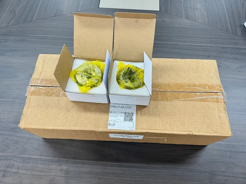
Inspect packaging for:
- direct metal-to-metal contact;
- inadequate protection of teeth;
- exposed machined surfaces;
- moisture;
- broken internal supports;
- mixed labels;
- intake/exhaust mixing;
- loose fasteners.
If corrosion prevention is required by the order, verify that the agreed protection is present.
Packaging inspection is especially important for distributors that will keep the part in stock before final sale.
20. Sample Inspection vs 100% Inspection
Not every incoming batch requires the same inspection level.
The plan should depend on factors such as:
- customer requirement;
- product criticality;
- supplier history;
- previous non-conformities;
- production change;
- drawing revision;
- batch size;
- agreed quality plan.
Some characteristics may be inspected on a sampling basis.
Others may require 100% confirmation if the commercial or technical risk justifies it.
The inspection level should be documented rather than decided informally at the inspection table.
21. A Practical Camshaft Phaser Incoming Inspection Sequence
A practical sequence is:
- confirm purchase-order and part reference;
- confirm intake/exhaust and any bank or side designation;
- confirm supplied scope;
- inspect packaging;
- inspect sprocket teeth and housing;
- inspect mounting and locating features;
- inspect accessible oil passages;
- inspect hydraulic mating surfaces;
- check locking behaviour if an approved non-destructive method exists;
- perform dimensional checks required by the inspection plan;
- perform functional testing only under a validated part-specific procedure;
- record results by batch;
- quarantine any non-conforming or uncertain parts;
- release only the accepted quantity to stock.
This order reduces the chance of spending time function-testing a part that is already wrong by position, OE reference or structure.
22. Suggested Incoming Inspection Record
A B2B receiving record can include the following fields:
| Inspection item | Result |
|---|---|
| Part number / OE reference | Pass / Fail |
| Intake / exhaust / bank position | Pass / Fail |
| Quantity and supplied scope | Pass / Fail |
| Packaging condition | Pass / Fail |
| Gear teeth | Pass / Fail |
| Housing and mounting surfaces | Pass / Fail |
| Central bore / fixing interface | Pass / Fail |
| Oil-port position | Pass / Fail |
| Oil-port cleanliness | Pass / Fail |
| Locking condition | Pass / Fail / Not tested |
| Dimensional checks | Pass / Fail / Per drawing |
| Functional test | Pass / Fail / Not required |
| Batch marking | Recorded |
| Non-conformity reference | If applicable |
| Inspector / date | Recorded |
“Not tested” is preferable to inventing a pass result for a characteristic that the receiving process cannot verify.
23. What Incoming Inspection Cannot Confirm
Basic receiving inspection cannot automatically prove:
- full hydraulic sealing performance;
- dynamic phasing response;
- long-term durability;
- material specification;
- heat-treatment condition;
- internal clearance;
- fatigue life;
- calibration;
- engine compatibility beyond the verified application data.
These characteristics require separate evidence, controlled testing or validated production records.
Incoming inspection should therefore be viewed as one layer of quality control, not a substitute for manufacturing validation.
24. When Should a Batch Be Quarantined?
A batch should be held for review when the inspector finds uncertainty that affects identity, installation or function.
Examples include:
- mixed intake and exhaust units;
- conflicting markings;
- oil-port geometry different from the approved sample;
- damaged locking behaviour;
- abnormal free movement;
- blocked oil passages;
- damaged teeth;
- damaged mounting surfaces;
- repeated contamination;
- unapproved drawing or product revision.
The next step is not automatically rejection.
The correct response may be:
- segregation;
- additional inspection;
- supplier clarification;
- drawing review;
- sample comparison;
- controlled functional testing;
- or formal non-conformity disposition.
The decision should be traceable.
Incoming Inspection Should Confirm Identity Before Function
The most effective camshaft phaser incoming inspection begins with a simple principle:
Confirm the correct part first.
Then inspect:
position → structure → locking condition → oil passages → mounting interfaces → required dimensions → validated function.
This order helps distributors and parts procurement teams identify wrong-position products, shipping damage, contamination and obvious mechanical inconsistencies before the phasers enter stock or reach a customer.
For detailed intake/exhaust and OE matching, use Wellgine’s Camshaft Phaser Identification Guide.
For the relationship between phasers, oil-control valves and the wider variable valve timing circuit, see the Variable Valve Timing System Guide.
Buyers reviewing available replacement applications can also explore Car Camshaft Phasers.
For project-specific inspection documentation, batch-control requirements and acceptance criteria, see Wellgine’s Quality Control information and confirm the applicable drawing, sample and quality specification before batch release.