A gerotor oil pump and a conventional gear oil pump both use positive-displacement pumping action to move engine oil, but their internal geometry is different.
A gerotor pump uses an inner rotor running eccentrically inside an outer rotor, while a conventional external gear oil pump uses two meshing gears rotating side by side inside the housing.
There is also an important terminology point:
A gerotor is technically a type of internal gear pump.
For this article, “gear oil pump” refers to the conventional external or spur-gear oil pump commonly contrasted with a gerotor in engine lubrication discussions.
For engine-parts buyers, this structural distinction matters because the two designs use different pumping elements, wear surfaces, shaft arrangements and inspection points.
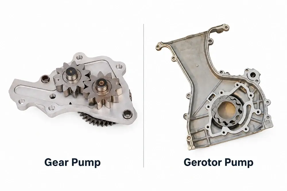
Gerotor vs Gear Oil Pump: Quick Comparison
| Comparison | Gerotor Oil Pump | External Gear Oil Pump |
|---|---|---|
| Pumping elements | Inner rotor and outer rotor | Two meshing gears |
| Rotor/gear arrangement | One rotor inside another | Two gears side by side |
| Tooth/lobe relationship | Outer rotor normally has one more lobe/tooth than inner rotor | Gears normally have matching tooth geometry |
| Chamber formation | Expanding and contracting spaces between inner and outer rotors | Oil trapped between gear teeth and housing |
| Main sealing relationship | Rotor-to-rotor, rotor-to-housing and side clearances | Gear-tip, gear-to-housing, side and gear-mesh clearances |
| Typical package | Compact concentric or near-concentric layout | Requires space for two gear centres |
| Drive arrangement | Often driven through the inner rotor | One gear is driven and drives the second gear |
| Inspection focus | Rotor profiles, tip/lobe contact, side clearance, housing | Gear teeth, shaft/bush condition, tip clearance, side clearance |
| Interchangeable by appearance? | No | No |
These differences describe pump architecture. They do not determine application compatibility on their own.
What Is a Gerotor Oil Pump?
A gerotor is a positive-displacement pump made from two rotating elements:
- an inner rotor;
- an outer rotor.
The inner rotor has fewer lobes or teeth than the outer rotor and rotates on an offset centre.
A common configuration therefore looks like:
Inner rotor → drives outer rotor → chamber volume increases → oil enters → chamber moves → volume decreases → oil exits
The continuous change in chamber volume produces the pumping action.
What Is a Conventional Gear Oil Pump?
A conventional external gear oil pump uses two gears mounted side by side.
One gear receives the mechanical drive.
That gear then drives the second gear.
As the gears separate near the inlet:
- chamber volume opens;
- oil enters;
- oil becomes trapped between the gear teeth and pump housing;
- rotation carries the oil around the outside of the gears;
- the teeth mesh again near the outlet;
- oil is displaced into the pressure circuit.
The oil does not normally pass directly through the meshing point between the two gears.
Instead, it travels around the outside of the gear pair.
Gerotor Structure: Inner Rotor and Outer Rotor
The defining feature of a gerotor is the rotor relationship.
A typical gerotor has:
- inner rotor;
- outer rotor;
- offset or eccentric centre relationship;
- inlet port;
- outlet port;
- housing;
- cover or side plate;
- drive interface.
The inner rotor normally has one fewer lobe than the outer rotor.
This tooth-count difference causes the cavities between them to continually change volume as they rotate.
Inlet Side
The spaces between the rotors become larger.
This creates the volume needed to draw oil into the pump.
Transfer Zone
Oil remains trapped inside the changing rotor cavities.
Outlet Side
The cavities become smaller.
The reduction in volume pushes oil towards the outlet.
This gives the gerotor a compact pumping element with relatively few major moving parts.
External Gear Pump Structure
An external gear pump normally includes:
- drive gear;
- driven gear;
- two gear shafts or shaft-support relationships;
- housing;
- inlet;
- outlet;
- side plate or cover;
- pressure-control mechanism where applicable.
The gears rotate in opposite directions.
Oil enters where the teeth move apart and is carried in the spaces between:
gear teeth + housing wall
until it reaches the outlet.
The teeth then re-mesh and displace the oil from the gear spaces.
Gerotor vs Gear Pump Oil-Flow Principle
Both designs are positive-displacement pumps.
That means both create oil flow by repeatedly creating and reducing enclosed fluid volumes.
The difference is where those volumes are formed.
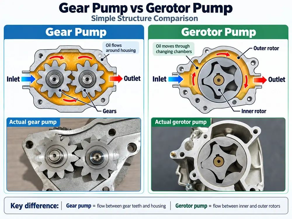
Gerotor
Oil is carried in cavities formed between:
inner rotor + outer rotor
Gear Pump
Oil is carried in cavities formed between:
gear teeth + pump housing
This structural difference affects:
- housing geometry;
- bearing or shaft support;
- inspection method;
- wear pattern;
- required manufacturing tolerances.
Drive Arrangement Differences
Pump type and pump drive are related, but they are not the same thing.
A gerotor may be:
- directly crankshaft-driven;
- gear-driven;
- chain-driven;
- driven from another engine shaft;
- integrated into a balance-shaft or front-cover assembly.
A gear oil pump may also use:
- gear drive;
- chain drive;
- intermediate shaft;
- camshaft-related drive;
- module drive.
Therefore, identifying a pump as “gerotor” does not tell the buyer how the complete pump assembly is driven.
Wellgine’s existing structure guide also separates internal pump design from external drive interface, which is important when comparing replacement assemblies.
Direct-Drive Gerotor Pumps
One packaging advantage of the gerotor design is that the inner rotor can be arranged around or directly coupled to a rotating shaft.
However, not every gerotor engine oil pump is crankshaft-driven.
For B2B identification, always confirm the actual:
- drive bore;
- spline;
- flats;
- gear;
- chain sprocket;
- shaft interface.
Gear-Pump Drive Layout
In an external gear pump, one gear is mechanically driven and transfers rotation through gear mesh to the second gear.
This creates several additional inspection relationships:
- drive-gear shaft condition;
- driven-gear shaft condition;
- shaft or bush clearance;
- gear alignment;
- tooth contact.
A similar external housing does not prove that two gear pumps use the same drive arrangement.
Gerotor Wear Points
The main gerotor inspection areas commonly include:
Inner-to-Outer Rotor Relationship
Check the rotor lobes for:
- scoring;
- pitting;
- abnormal contact;
- embedded debris;
- deformation.
Rotor-to-Housing Clearance
Wear can increase internal leakage.
Rotor End Clearance
Excessive clearance between the rotor faces and cover/housing can reduce volumetric efficiency.
Housing Surfaces
Inspect for:
- grooves;
- scoring;
- debris damage;
- cavitation-like surface damage where applicable.
Drive Interface
Check the inner rotor or drive connection for:
- rounding;
- cracking;
- fretting;
- abnormal wear.
Exact clearance limits must come from the application-specific service or drawing specification.
External Gear Pump Wear Points
A conventional gear pump has a different inspection focus.
Gear Teeth
Check for:
- pitting;
- scoring;
- chipped teeth;
- abnormal flank wear.
Gear-Tip-to-Housing Clearance
Excessive clearance increases internal leakage.
Side Clearance
Gear face and cover/housing wear can allow pressure leakage.
Shafts and Bushes
Where applicable, check:
- shaft wear;
- bush wear;
- radial movement;
- misalignment.
Drive Gear
Inspect the external drive interface separately from the pumping teeth where the design uses one.
Again, specifications vary by engine and pump architecture.
Why Clearance Matters in Both Designs
Neither a gerotor nor a gear pump creates a fixed pressure independently of the rest of the lubrication system.
Both primarily create oil flow.
Pressure develops because the engine lubrication circuit resists that flow.
As wear increases internal clearances, more oil can leak internally from the pressure side towards the inlet side.
This can reduce useful pump delivery, especially under conditions where:
- oil is hot;
- viscosity is lower;
- engine clearances are increased;
- pump speed is low.
A low-pressure symptom therefore does not automatically identify whether a rotor set, gear set, bearing clearance or another lubrication component is responsible.
Gerotor vs Gear Pump: Noise and Flow Smoothness
Gerotor pumps are often associated with relatively smooth oil delivery because the inner and outer rotor chambers change volume continuously.
External spur-gear pumps have discrete tooth engagement and disengagement events.
However, this should not be used as a field-identification rule.
Engine installation, housing design, tooth geometry, speed and lubrication conditions all affect actual noise.
Is a Gerotor Always Better Than a Gear Pump?
No.
The correct design depends on the engine and lubrication-system requirements.
The two architectures involve different compromises in:
- packaging;
- shaft arrangement;
- displacement;
- flow behaviour;
- manufacturing;
- engine integration;
- serviceability.
A pump should therefore be evaluated against its intended engine application rather than by treating one architecture as universally superior.
For replacement sourcing, the correct OE-reference and application match matters more than a generic pump-type preference.
Gerotor vs Gear Pump Failure Symptoms
The symptom level can overlap significantly.
Either pump type may be associated with:
- low actual oil pressure;
- delayed pressure build-up;
- lubrication-related noise;
- oil-pressure warning;
- inadequate pressure at specified RPM.
These symptoms do not identify the pump type or failure point.
Other causes can include:
- pickup restriction;
- pickup seal leak;
- incorrect oil viscosity;
- excessive engine bearing clearance;
- pressure-relief valve fault;
- oil-pressure sensor fault.
Therefore, diagnosis must precede product selection.
Inspection: Gerotor Pump
For an incoming or removed gerotor pump, applicable inspection may include:
- Confirm OE reference and engine code.
- Confirm inner and outer rotor profiles.
- Inspect rotor faces and lobe surfaces.
- Check the pump housing for scoring.
- Check cover condition and flatness where applicable.
- Check side and rotor clearances against the approved specification.
- Inspect the drive interface.
- Confirm inlet and outlet passage positions.
- Check pressure-relief or control components.
- Confirm supplied seals and assembly scope.
Do not invent a universal clearance specification.
Use:
- OEM service information;
- approved engineering drawing;
- validated reference sample;
- agreed project specification.
Inspection: Gear Oil Pump
For a conventional gear pump, inspection may include:
- Confirm OE reference and application.
- Inspect gear teeth and flanks.
- Inspect drive and driven shafts.
- Check bushes or shaft bores where fitted.
- Check gear-tip clearance.
- Check gear side clearance.
- Inspect cover and housing wear.
- Confirm gear alignment and rotation.
- Check pressure-relief components.
- Confirm drive gear, pickup and supplied scope.
The measurement method must match the actual pump design.
Gerotor vs Gear Oil Pump Inspection Checklist
| Inspection item | Gerotor | Gear pump |
|---|---|---|
| Inner/outer pumping element | Rotor lobes | Gear teeth |
| Main geometry check | Rotor profile and eccentric relationship | Gear mesh and centre relationship |
| Housing wear | Rotor bore / chamber | Gear cavity |
| End/side clearance | Rotor face clearance | Gear face clearance |
| Radial clearance | Rotor/housing relationship | Gear tip/housing relationship |
| Shaft inspection | Depends on drive architecture | Often important for both gears |
| Drive interface | Inner rotor / spline / shaft / external drive | Drive gear shaft / external gear / sprocket |
| Pressure-control parts | Inspect if integrated | Inspect if integrated |
| Application confirmation | OE + engine code | OE + engine code |
How to Identify Which Pump You Have
Do not identify an oil pump from the front housing alone.
A Gerotor Can Usually Be Recognised Internally By
- inner lobed rotor;
- outer ring rotor;
- one-tooth/lobe difference;
- eccentric rotor relationship.
An External Gear Pump Can Usually Be Recognised By
- two separate gears;
- side-by-side centres;
- conventional external gear teeth;
- two shaft positions or supporting bores.
However, many replacement oil pumps are sold as closed assemblies.
If the internal elements cannot be inspected, confirm using:
- OE number;
- engine code;
- housing;
- drive interface;
- inlet/outlet locations;
- rear mounting face;
- verified product drawing;
- original pump photographs.
Do Not Confuse Pump Type with Assembly Type
A gerotor pumping element can be integrated into:
- front cover;
- balance-shaft module;
- variable-displacement mechanism;
- crankshaft-driven pump assembly.
Likewise, a gear pump can be supplied as:
- standalone pump;
- chain-driven assembly;
- housing-integrated unit.
This is why descriptions such as “gerotor oil pump” do not define the complete commercial scope.
For broader assembly definitions, see Engine Oil Pump Structure: Diagram, Parts and Assembly Types.
B2B Matching: What Buyers Should Confirm
Before comparing quotations for either pump type, confirm:
- complete OE number;
- verified superseding number where applicable;
- engine code;
- vehicle application and market;
- gerotor or gear architecture;
- drive method;
- housing depth;
- mounting face;
- bolt pattern;
- inlet and outlet location;
- relief/control valve provision;
- pickup interface;
- supplied assembly scope;
- front, rear and drive-side photographs;
- required quantity.
A rotor or gear design that looks similar does not establish interchangeability.
Pump Inspection for Batch Purchasing
For B2B incoming or pre-shipment inspection, the relevant checks should follow the approved product specification.
Depending on the pump design and project, applicable checks can include:
- product identity;
- OE reference;
- casting and housing condition;
- rotor or gear surface condition;
- drive-interface structure;
- mounting dimensions;
- inlet and outlet passages;
- rotation and interference;
- pressure-control components;
- cleanliness;
- assembly completeness;
- packaging and traceability.
Frequently Asked Questions
Is a Gerotor an Oil Pump or a Gear Pump?
A gerotor is a type of positive-displacement internal gear pump. In automotive terminology it is often discussed separately from a conventional external or spur-gear oil pump because the internal geometry is substantially different.
What Is the Main Difference Between a Gerotor and a Gear Oil Pump?
A gerotor uses an inner rotor rotating eccentrically inside an outer rotor. A conventional external gear pump uses two meshing gears mounted side by side.
How Does a Gerotor Pump Move Oil?
The spaces between the inner and outer rotors expand near the inlet, carry oil around the pump and contract near the outlet.
How Does a Gear Oil Pump Move Oil?
Oil enters where the gear teeth separate, is trapped between the teeth and housing, travels around the outside of the gears and is discharged where the gears re-mesh.
Which Pump Is Quieter?
Gerotor designs are generally associated with smoother flow and lower tooth-mesh pulsation, but actual engine noise depends on the full pump and engine installation.
Is a Gerotor Always Crankshaft-Driven?
No. A gerotor describes the pumping element, not the drive method. It may be crankshaft-, chain-, gear- or module-driven depending on the engine.
Can Gerotor and Gear Oil Pumps Be Interchangeable?
Not simply because they perform the same lubrication function. Housing, drive, port positions, displacement, control strategy, OE reference and engine application must all match.
What Should Be Inspected on a Gerotor Pump?
Typical checks include inner and outer rotor surfaces, rotor-to-housing relationship, end clearance, housing scoring, drive interface and integrated pressure-control components.
What Should Be Inspected on a Gear Oil Pump?
Typical checks include gear teeth, shafts or bushes, gear-tip clearance, gear side clearance, housing wear and drive interface.
Engine Oil Pump Sourcing
For a gerotor or gear oil-pump sourcing enquiry, provide Wellgine with:
- OE reference;
- engine code;
- vehicle application;
- pump front and rear photographs;
- drive-side photograph;
- internal rotor or gear photograph where available;
- required assembly scope;
- quantity.
Wellgine supplies selected engine oil pumps and pump assemblies for international aftermarket and B2B sourcing.